3D Wii Manipulation of Photos (WIMP)
Videos
Here are some example videos which demonstrate how to use the program.

- This video (in MPEG format, 768x280 pixels and 128 seconds) shows the screen video capturing and the person who is operating the program synchronously. Above is a screen capture of the video.
- This video (in MPEG format, 352x240 pixels and 128 seconds) shows the screen video capturing only.
- This video (in MPEG format, 352x240 pixels and 128 seconds) shows the person who is operating the program only.
Hardware photos
Headset


- Here are some photos showing an example 'head set' using 3 LEDs. It is made of one pair of glasses (cheap plastic safety glasses) and 3 IR LED circuits attached to the glasses.
- In order to increase the positioning accuracy, those 3 LEDs must be placed in the same line. As long as you fulfill this requirement, then your glasses design is up to you.
- In our design, two of the 3 IR LED circuits are enclosed in two candy cylinders which are placed on the two sides of the glasses. The middle IR LED circuit is a simple closed circuit.
IR LED circuit inside the candy cylinder


- The left photo shows the IR LED circuit taken out from the candy cylinder.
- The right image shows the IR LED circuit diagram of the circuit shown in the photo on the left. This website can help you to design your own IR LED circuit.
IR LED pen


- The left photo shows the IR LED pen which is used to perform gestures.
- The right image shows the IR LED pen circuit diagram of the circuit shown in the photo on the left. A resistor is not needed in this circuit because the battery voltage is suitable for the LED and will not damage the LED. This website can help you to design your own IR LED circuit.
Software screen shots
IR Display Screen Shot

- This screen shot shows the image captured from the "IR Display" program when there are four IR LEDs directed toward the Wiimote.
- The upper three yellow circles come from the headset, they lie on a straight line.
- The lower yellow circle comes from the IR LED pen.
- The maximum number of IR signals that the Wiimote can support is four.
WIMP Screen Shots (Folder Selection Level)


- The left one is the screen shot just start up.
- The right one shows the user is selecting the folder using the IR LED pen.
WIMP Screen Shots (Photo Selection Level)
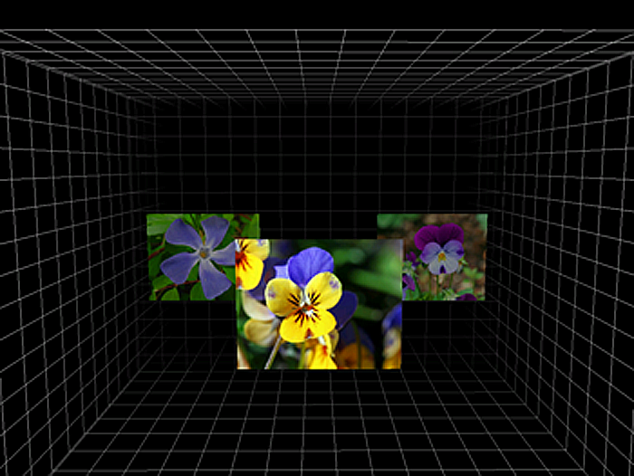

- These images are taken when the user is selecting the photo in the "Photo Selection Level" using the IR LED pen.
WIMP Screen Shots (Photo View Level)


- The left photo is one of the photos included when you download the program.
- The right one shows the color negation effect is applied on the same photo using WIMP.

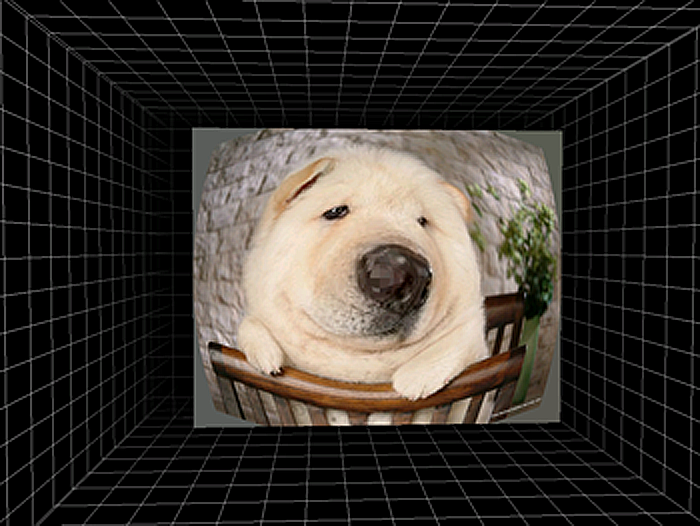
- The left photo is another one of the photos included when you download the program.
- The right one shows the fish eye effect is applied on the same photo using WIMP.